Tag Archive for: transformer

Diagnostics and monitoring of transformers: fault prevention

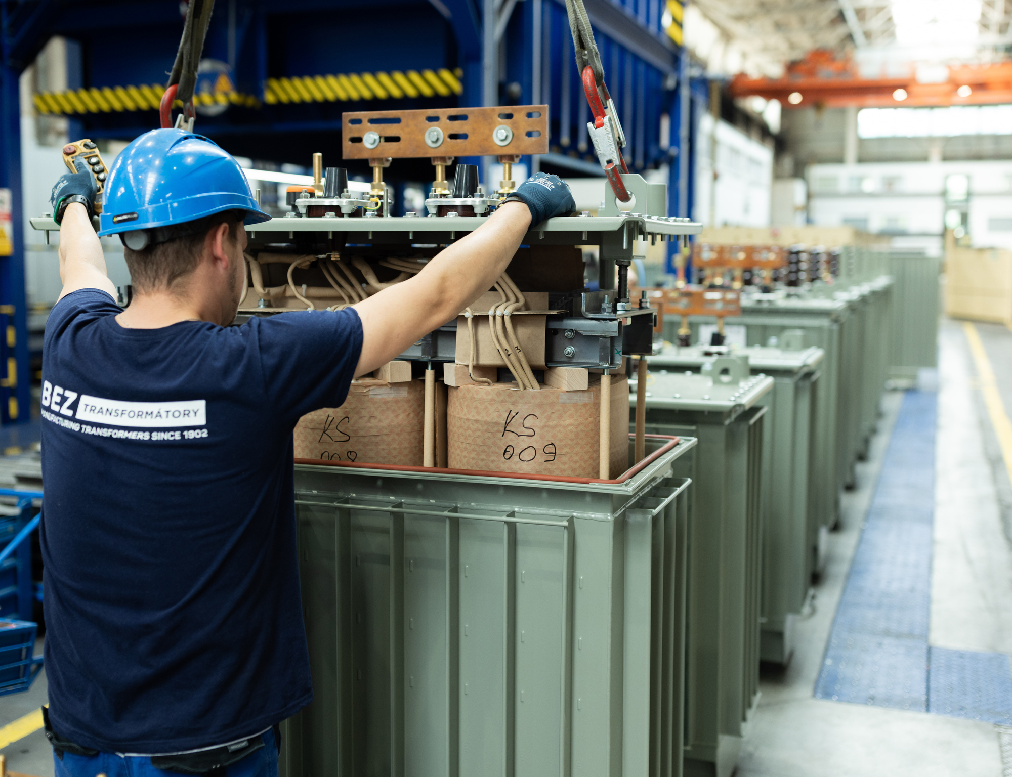
In the modern power environment, where more and more emphasis is being placed on efficiency and continuous operation, transformer monitoring is becoming a necessity. Diagnostic systems therefore reflect the specific needs of each type of machine, from conventional oil-immersed to special transformers.

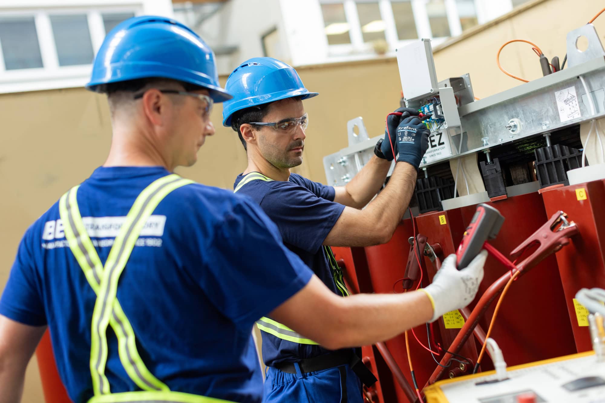
Why is transformer monitoring important?

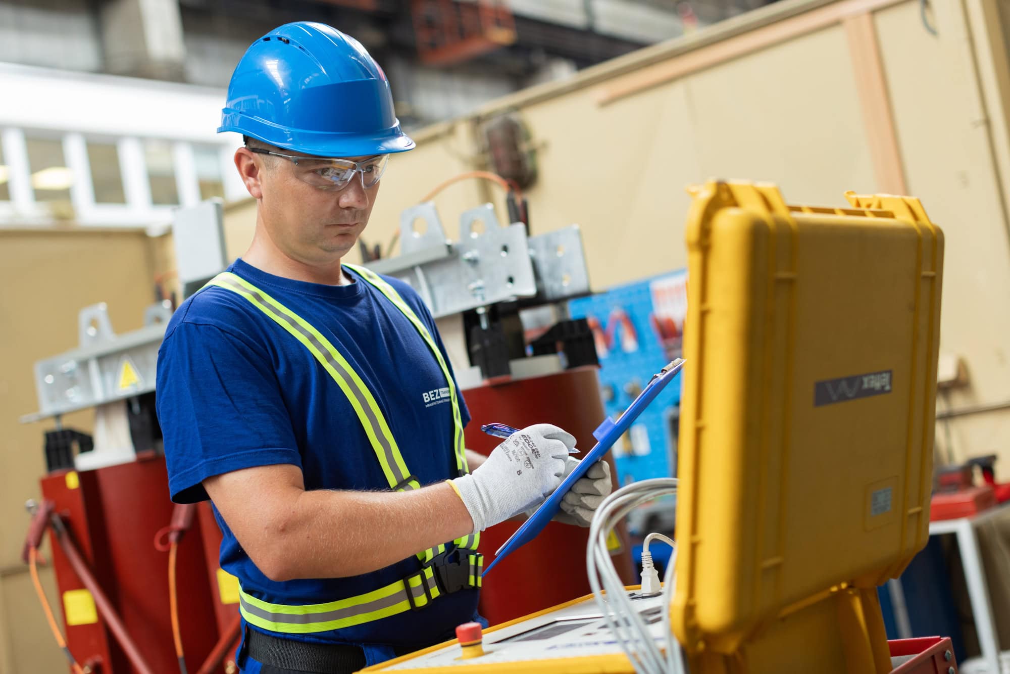
In the past, maintenance was carried out reactively, that is, only when a problem arose was it dealt with. However, the present requires a predictive approach. However, modern technology allows us to “see inside” the machine without having to shut it down. Real-time monitoring of transformers can therefore identify up to 90% of incipient faults in their embryonic stage, extending the life of the equipment by decades.

Tailored diagnostics: from oil to renewables
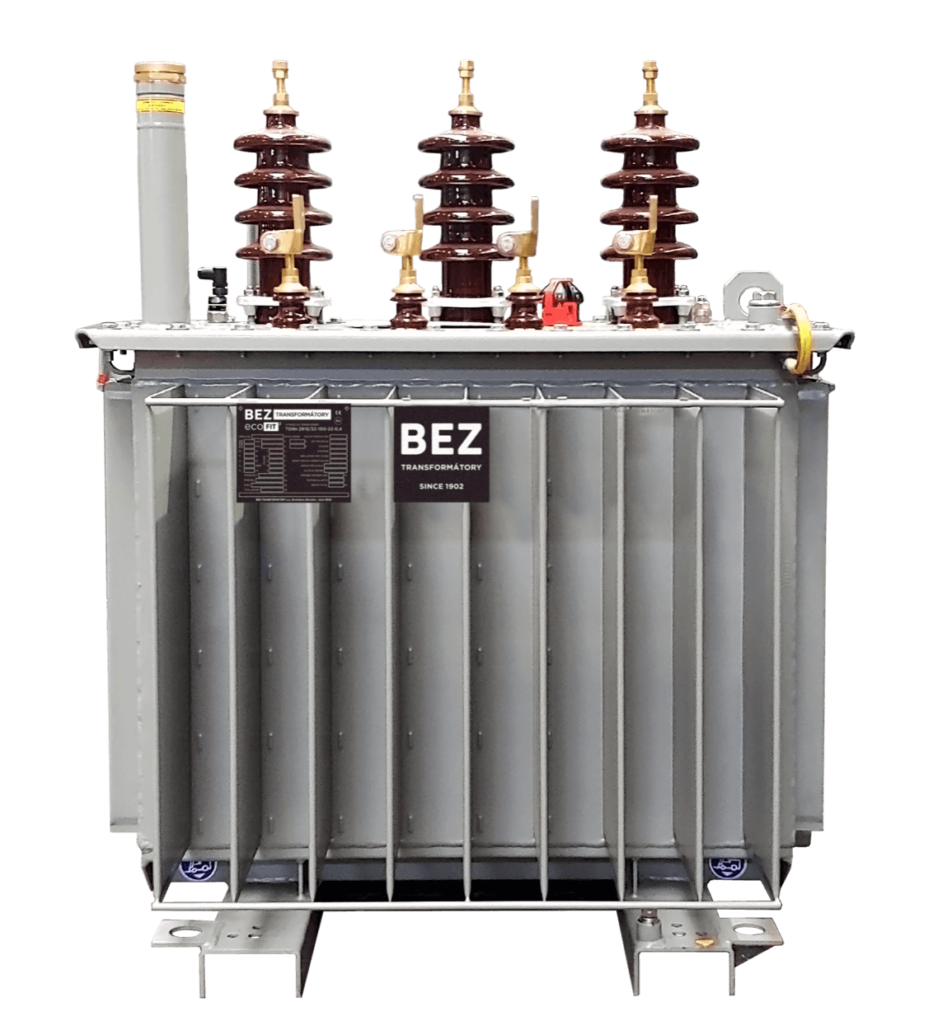
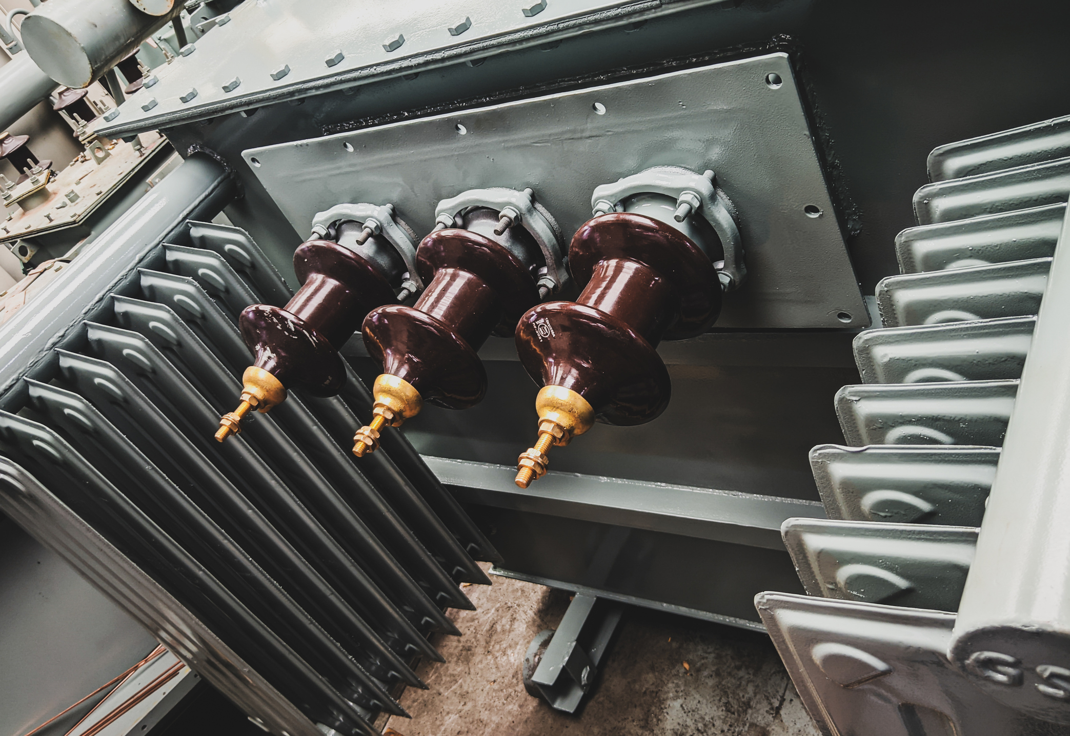
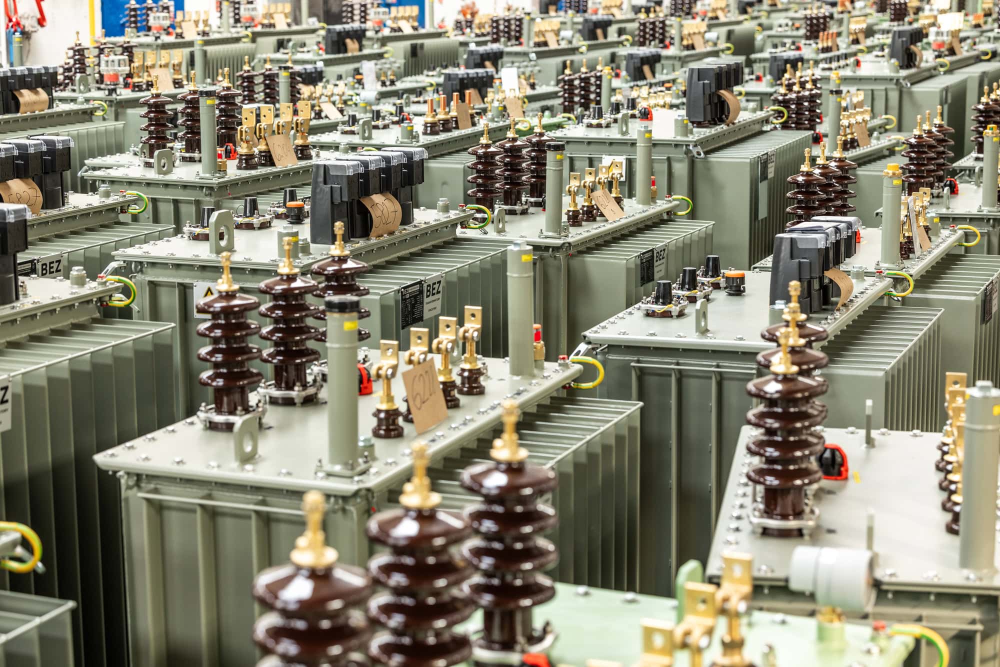
Oil Transformers

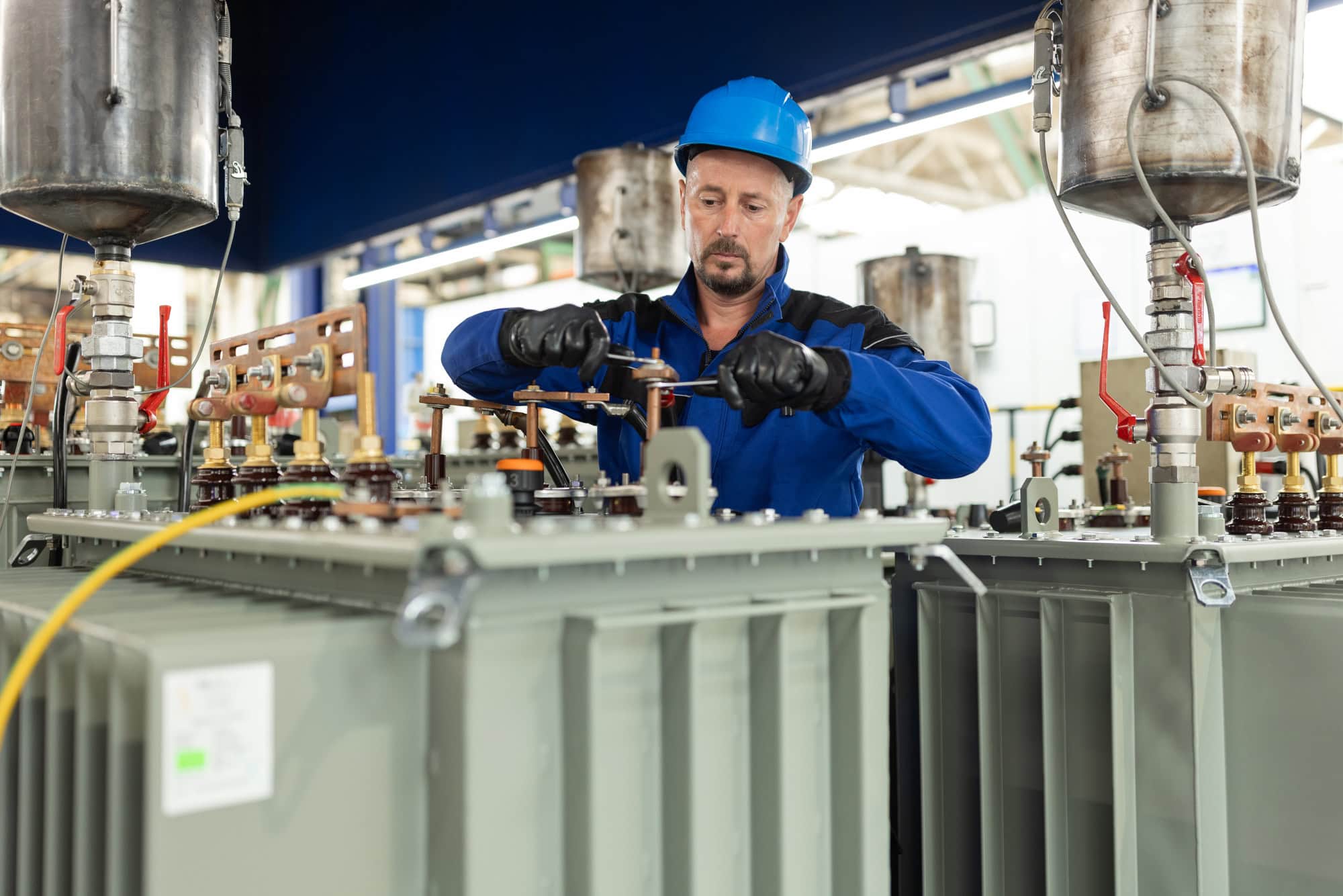
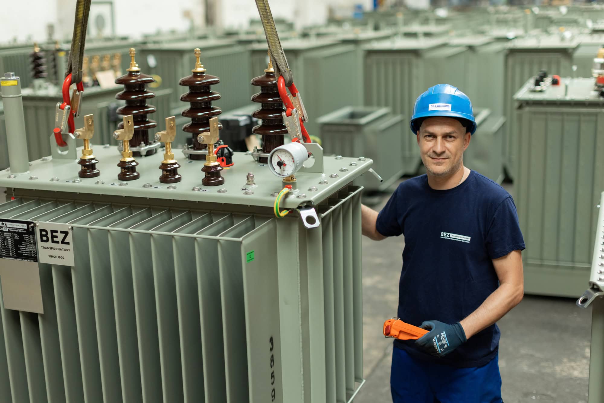
For oil-immersed transformers, the key indicator of the condition is the insulating liquid. The gases dissolved in the oil are analyzed. The presence of specific gases (hydrogen, methane, acetylene) accurately indicates the type of fault, from electrical discharges to thermal overload. The water content of the oil is also monitored. This is critical for maintaining dielectric strength and preventing degradation of the paper insulation.
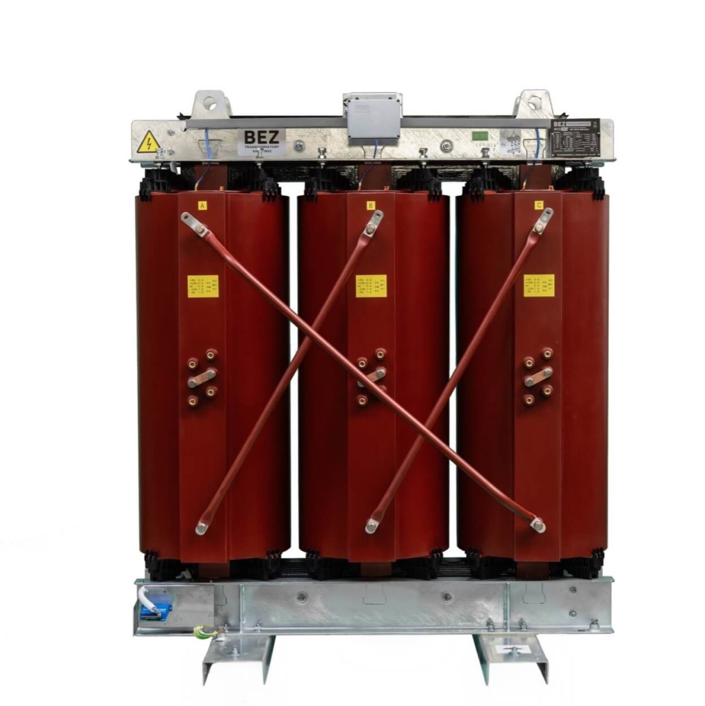
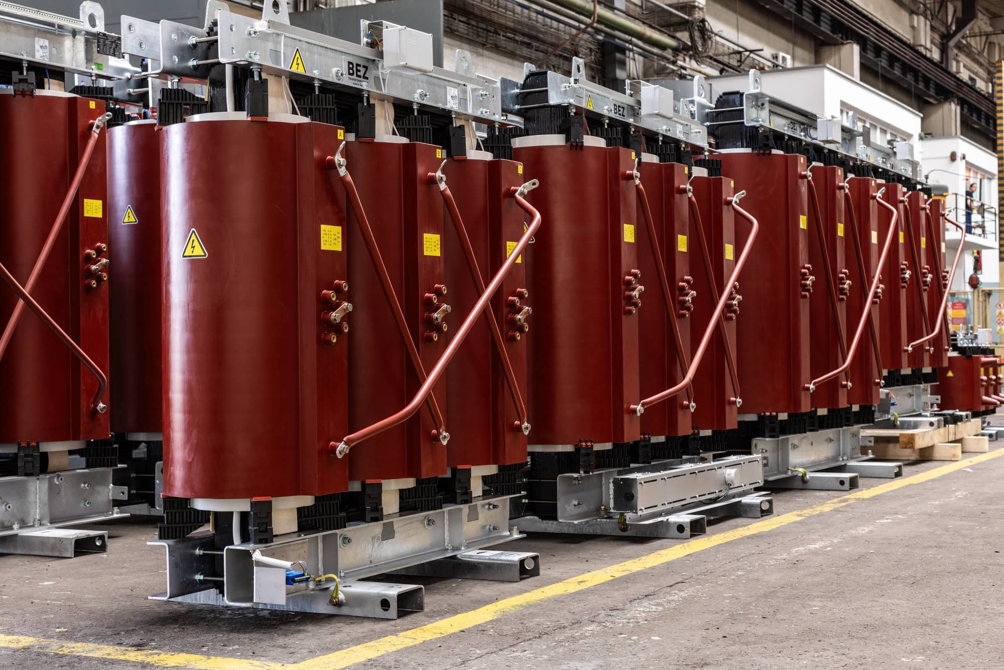
oil transformers, transformer monitoring, oil transformer manufacturing, transformer warehouse

Dry transformers

Dry transformers, insulated with epoxy resin, are ideal for areas with high fire safety requirements. Monitoring of thermal points is important. Using PT100 or fibre optic sensors, the winding temperature is monitored in real time, preventing thermal degradation of the resin. Partial discharge measurements are also an effective method. This method detects in time micro-cracks in the insulation that could lead to a fatal short circuit.

dry transformers, transformer monitoring,

Special transformers

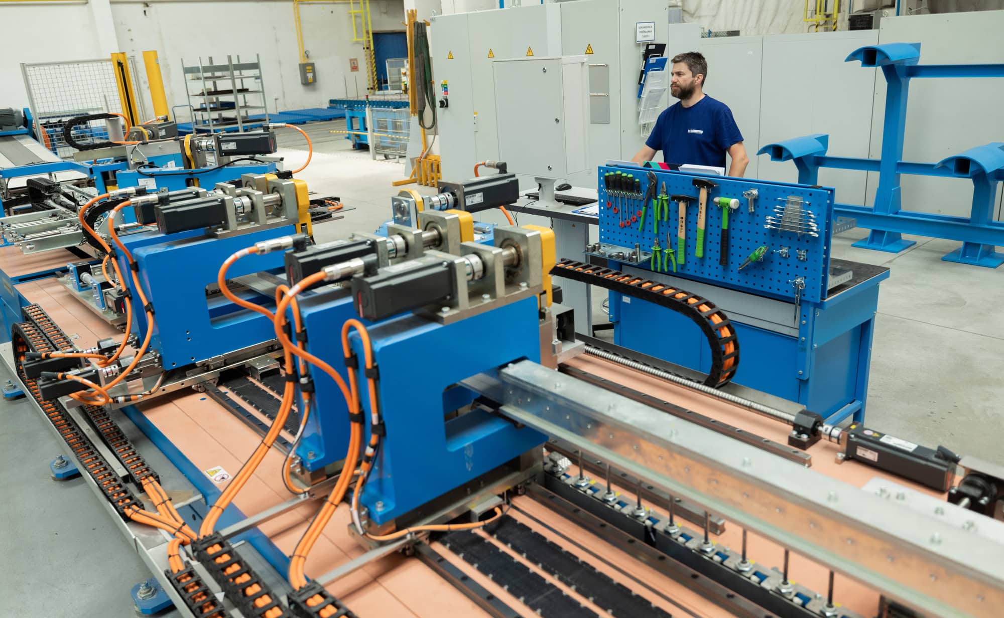
In industrial plants, transformers face high current surges and harmonic distortion. Therefore , we analyze the mechanical vibration. We monitor the stability of the core and windings, which are stressed by dynamic forces. We do not neglect the monitoring of tap changers. Monitoring the condition of the contacts directly under load eliminates the risk of mechanical failure.

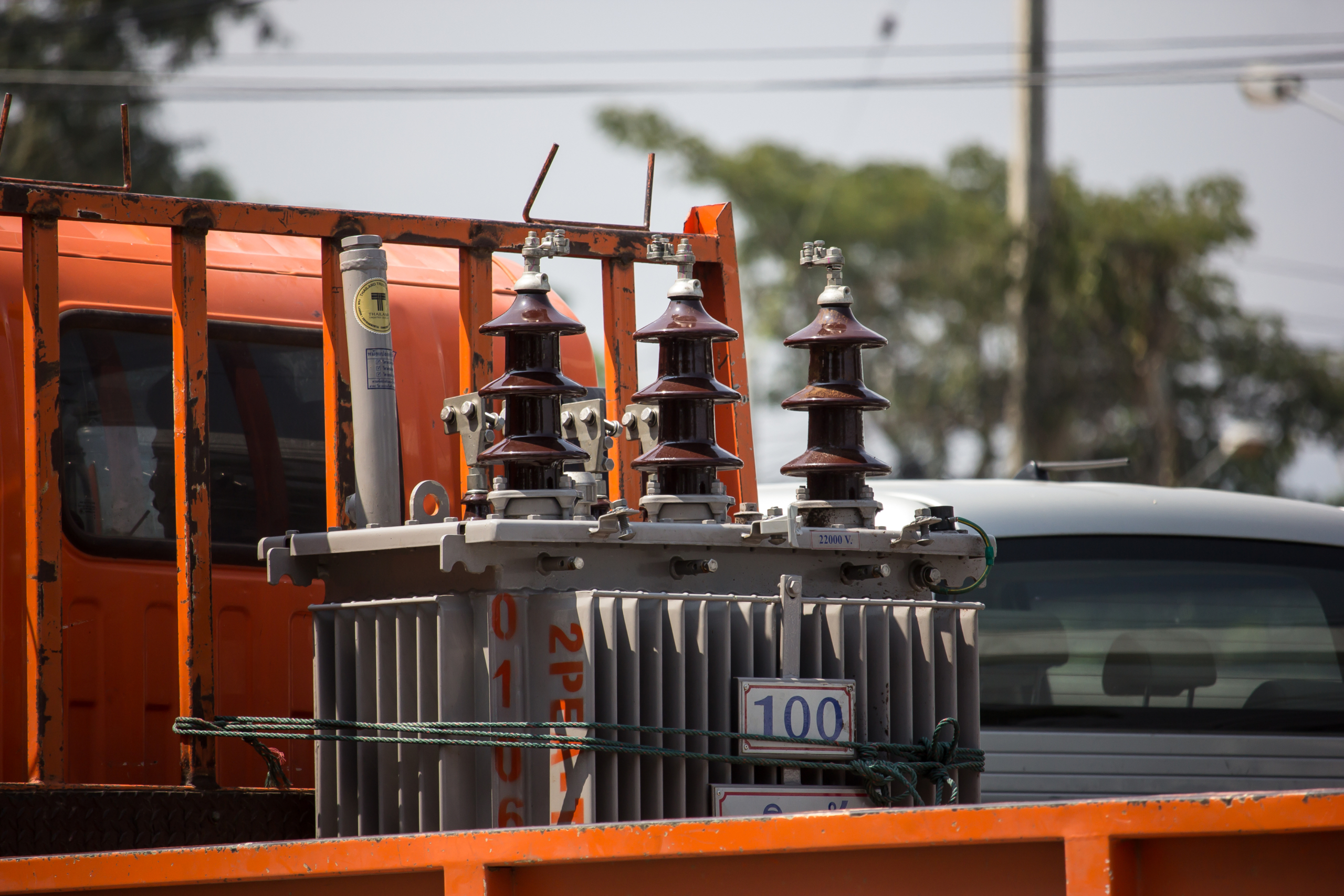
Transformers for renewable energy

Photovoltaic and wind power plants present a new challenge for transformers due to cyclical and unstable loads. Adaptive monitoring is important. Our RES systems take into account frequent temperature fluctuations and variable power output to optimize the operation of substations in smart grids.

Benefits of systematic monitoring of transformers for operation

The introduction of modern diagnostic methods is not just about technical measurements, but about strategic asset management. The correct interpretation of data brings many benefits to operators:

  • Reduce operating costs: it allows you to switch to targeted service based on actual status instead of fixed time revisions, which can be inefficient.
  • Investment optimisation: accurate data on wear rates and residual lifetime allows managers to better plan infrastructure renewal and avoid premature purchases of new machines.
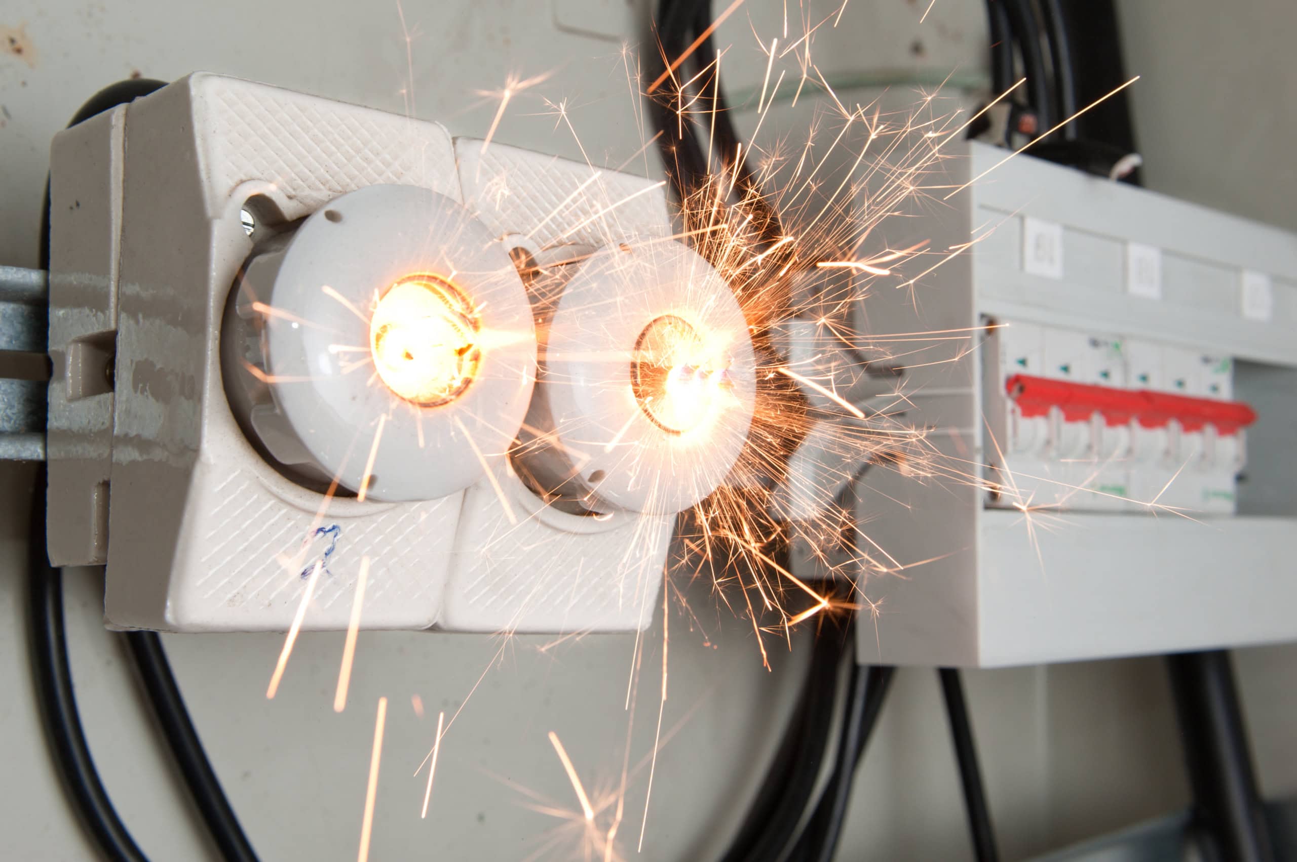
  • Enhancing safety and ecology: continuous monitoring minimizes the risk of catastrophic failures, fires or environmental accidents associated with oil spills.

In today’s power industry, investing in transformer monitoring is a necessary step to ensure business continuity. At a time of long lead times for new technologies and high energy costs, keeping existing infrastructure in tip-top shape is the most effective route to grid sustainability and stability.

Low-loss transformers: modern technologies and materials

Low-loss transformers and energy efficiency have become a global priority. In particular, the focus is on minimising losses. Every percentage reduction in losses translates into massive energy savings at the level of the entire distribution network, which has a direct economic and environmental impact. Lower losses not only mean lower operating costs, but also a significant reduction in CO 2 and less burden on the environment. This trend has also been formalised legislatively, notably through the stringent Commission Regulation (EU) 2019/1783 (Ecodesign 2021, Stage 2), which sets uncompromising requirements for transformer losses.

Understanding transformer losses

We divide transformer losses into two main groups, which have different sources and require different design solutions.

1. Idle losses (iron losses)

These losses occur in the magnetic core of the transformer. They are constant and do not depend on the load. They are consumed by the transformer whenever it is connected to the grid, even if it is not transmitting any power. Hysteresis losses are caused by the constant change in the direction of the magnetic field (remagnetization) of the core material. They are related to the quality of the magnetic sheets and their loss characteristics. Eddy current losses are due to induced currents directly in the core material, which are generated by the variable magnetic flux. They are reduced by dividing the core into thin insulated sheets (lamination).

2. Short-circuit losses (losses in windings)

Short-circuit losses mainly occur in the transformer winding (in copper or aluminum). These losses are directly related to the magnitude of the current flowing through the transformer and are therefore load dependent. They are caused by the winding resistance. As the load on the transformer increases, the current increases and the losses increase with the square of the current.

Innovative materials for loss reduction in low-loss transformers

The key to radically reducing both types of loss lies in the selection and processing of superior materials. At BEZ TRANSFORMÁTORY , we use top-quality steel with a grain-oriented structure (CRGO) that ensures easy passage of the magnetic flux. These cores also utilize advanced sheet metal shearing and folding technology, such as step-lap, which minimizes transient resistive losses at the corners.

The amorphous metal material has an unstructured atomic structure, similar to glass. The lack of a crystalline structure reduces the energy required to remagnetize the material, resulting in extremely low hysteresis losses. Low-loss transformers with an amorphous metal core can reduce no-load losses by up to 66% compared to conventional CRGO steel, delivering unmatched standby efficiency. We use either copper, which has an extremely low resistivity, or aluminium, which offers a favourable price/performance ratio, in the manufacture of the windings. The key is to use conductors with the ideal cross-section with respect to the current flowing through them. A larger cross-section naturally reduces resistance and therefore heat loss. Optimizing the cross-section of the conductors becomes the most important design element in the fight against load losses.

low-loss transformers, innovative materials, loss reduction

Advanced technologies and design solutions for low-loss transformers

Low losses are not just a matter of materials, but also require precise design and manufacturing technologies to ensure optimum use of these superior raw materials. We use advanced shearing lines with Step-Lap technology to produce magnetic cores. This method ensures extremely precise lamella joints at the corners of the core, minimizing air gaps and reducing local eddy current and hysteresis losses at magnetic flux bending points.

The winding design, especially for power transformers, must minimize stray losses. These are additional losses caused by leakage magnetic flux that induces currents in the surrounding metal parts of the transformer (e.g. clamping frames). We use special shielding and optimize the spatial arrangement of the windings to direct the flux and suppress these unwanted losses.

Low-loss dry-type transformers with cast insulation represent a modern alternative to traditional oil-cooled transformers and bring significant low-loss and safety benefits. Instead of flammable oil, they use epoxy resin ( EP) to pot the windings. This resin is environmentally friendly, flame retardant and reduces the risk of fire, thereby increasing the safety of operation. Cast insulation technology allows more precise placement of windings, minimizing internal resistance and increasing mechanical stability.

Proper heat dissipation is also key. Higher operating temperature increases winding resistance, which directly leads to an increase in short-circuit losses. We therefore use efficient natural or forced cooling systems to keep the transformer at optimum operating temperature. We ensure maximum flow of coolant (air or oil) around the windings and core, thus achieving a stable low temperature and the transformer consistently operates under the lowest possible loss conditions.

low-loss transformers, advanced technology

Eco-design and the future of low-loss transformers

For BEZ TRANSFORMÁTORY, meeting the EU’s Ecodesign requirements is a minimum standard, not a target. Our innovations in materials and design ensure that our low-loss transformers not only meet the strict loss limits in place from 2021 (Stage 2), but many even exceed them, providing our clients with future-ready solutions.

Transformers in photovoltaics: choosing the right transformer for maximum efficiency of a photovoltaic power plant

Discussions of green energy often focus on photovoltaic panels, which convert sunlight into electricity, and inverters, which transform direct current into alternating current. While these components are crucial, there is another and often overlooked link in the chain between the PV array and our homes or industrial plants: the transformer. But transformers in PV are not limited to raising the voltage.

The role of transformers in photovoltaic power plants

Photovoltaic systems, whatever their size, have a fundamental challenge: the energy they generate must be adapted to meet the stringent requirements of the electricity grid.

Increasing tension

Photovoltaic panels produce direct current (DC), which the inverter then converts to alternating current (AC). However, this AC current is generated at a relatively low voltage. While this would be sufficient for normal domestic use, it is inefficient and uneconomical for transmission over medium and long distances to distribution points. Therefore, a transformer comes into play. It receives AC current from inverters and its main task is to radically increase the voltage to grid level (e.g. 22 kV, 35 kV, or up to 110 kV for large parks). Without this step, there would be huge energy losses. This is because higher voltages allow power to be transmitted at a much lower amperage, thus minimising losses in the lines.

Insulation and system safety

The transformer also performs a safety function. It provides galvanic isolation of the photovoltaic system from the distribution network. This decoupling protects the expensive and sensitive inverters from surges, surges and faults that can occur on the grid, while ensuring that faults in the solar park do not critically affect the stability of the utility grid.

transformer in photovoltaics

Typology of transformers in photovoltaic systems

BEZ TRANSFORMÁTORY offers two main types of transformers for photovoltaic parks: oil-immersed and dry-type transformers.

Oil Transformers for Renewable Energy

Oil-cooled transformers are cooled by mineral oil and are the most widely used type in the long term, particularly suitable for outdoor PV park environments where they can withstand adverse weather conditions. Thanks to oil cooling, they can dissipate heat efficiently even under higher loads and offer excellent reliability and extended service life.

oil transformer

Dry-type transformers for renewable energies

Dry-type transformers do not use liquid dielectric, but are cooled by air. They are ideal for indoor and container stations where there are increased demands on fire safety, for example in close proximity to inverters or in densely built-up areas. They are more environmentally friendly, require less maintenance and eliminate the risk of oil leaks.

dry transformer

Impact of transformers on the efficiency and stability of power transmission

The quality of the transformer directly determines the economic success and technical reliability of the entire solar project.

Efficiency and loss minimisation

As we have already mentioned, loss minimisation is a key factor. This is because by increasing the voltage, the current drops, which dramatically reduces the heat loss. Transformers with low intrinsic losses maximize the amount of energy produced that actually reaches the consumer. Thanks to their robust design and life expectancy in excess of 30 years, transformers guarantee a long-term return on investment and reliable operation of the PV park in a variety of climatic and operating conditions. The investment in a transformer with low no-load and short-circuit losses will thus pay for itself many times over during the long lifetime of the project.

Network stability and quality control

Photovoltaics, although a clean source, can present challenges in the form of voltage fluctuations and THD harmonic distortion generated by inverters. Therefore, advanced transformers have systems that allow smooth and automatic voltage regulation, thus maintaining grid stability even with rapid changes in sunshine. In addition, the transformer helps to dampen and filter harmonic currents. This ensures that the energy supplied to the distribution system is clean and meets all standards.

transformer in photovoltaic power plant

The challenge of the future

As PV expands and integrates into smart grids and battery storage, the demands on transformers will only increase. Their quality design, ability to handle fluctuating loads and minimize losses are essential for a successful and sustainable transition to green energy.

If you are currently designing or optimizing your PV park and are looking for a customized solution that guarantees low losses and long lifetime, contact us. Our technical specialists will be happy to help you with your selection.

Transformer life: how to extend its operation?

Technical, operational and environmental factors determine how long a plant will operate reliably. Deteriorated insulation, overloading or inadequate maintenance can lead to reduced performance, higher losses and ultimately premature failure. Thus, reduced transformer lifetime is not just a technical problem. It also represents a significant financial loss, as the replacement or overhaul of equipment is one of the most costly interventions in the electricity industry.

Factors affecting transformer life

Transformer life is the result of the interplay of a number of physical, chemical and operational phenomena. The following factors are among the most significant.

Thermal stress and overload

If the equipment is operated at a higher temperature than specified by the manufacturer for an extended period of time, the degradation of insulation materials is accelerated. Therefore, make sure that the transformer is properly sized and avoid overloading it for long periods of time. Even short-term overloading can leave lasting effects if repeated too often.

Quality of the insulation system

If the condition of the insulation system deteriorates, not only the electrical strength but also the overall service life of the transformer is reduced. The most common problems are moisture, oil oxidation and contamination by dirt. For this reason, regularly check the physicochemical properties of the insulating oil. Prevention in this case is much cheaper than subsequent repair.

Vibration and mechanical stress

Prolonged vibration can lead to loosening of windings, damage to connections and weakening of the core. Proper design is therefore the basis for a long service life. In practice, it is recommended to check the fit of the screws and damping elements regularly, especially after major short circuits or equipment transports.

Influence of the external environment

Dust, moisture, corrosive environments or extreme temperatures can accelerate the ageing of materials and reduce insulation properties. In addition, transformers located outdoors are exposed to sudden changes in temperature, UV radiation and weathering. Therefore, use appropriate protective coatings, seals and filtration systems. Proper ventilation and regular leakage checks are also important, especially for oil-immersed transformers.

Quality of installation and pre-commissioning checks

Improper cable connections, loose contacts or neglected cooling can significantly shorten the operating life of the transformer. The key is therefore professional installation, careful checking before start-up and adherence to the manufacturer’s recommendations throughout the lifetime of the transformer.

Factors Affecting Transformer Lifetime, Quality of Installation and Inspection Before Starting

Inspections and revisions as the key to long transformer life

Even the best quality transformer needs regular checks and inspections. A properly set up inspection program can extend the life of a transformer by decades while increasing its efficiency by reducing energy losses and minimizing the risk of failure. Inspections and revisions should include the following steps:

  • oil tightness check,
  • analysis of oils and gases,
  • electrical testing, protection calibration and transformer earthing,
  • control of noise, vibration and ambient temperature,
  • correct setting and securing of the tap changer.

The investment in inspections and revisions always pays off in lower operating costs, higher transformer efficiency and, above all, a longer and more reliable service life.

Preventive measures to reduce wear

Although the transformer has its design limits, the right approach can significantly extend its life and maintain high efficiency throughout operation. Preventive measures do not only mean regular inspections, but also strategic decisions on operating methods, upgrades and operator behaviour:

  • proper operation and load management,
  • modernisation and technical improvements,
  • temperature and humidity control,
  • operator training and competence,
  • strategic planning and predictive maintenance.

Preventive measures are not just a set of technical steps, but an overall philosophy of how to approach a facility. If applied consistently, they can extend the life of a transformer by decades while reducing both energy and service costs.

Transformer voltage transformer: key role and practical application

Without transformers, electricity could not travel efficiently and safely from the power station to your socket, nor would most industrial machinery work. But all functionality depends on one key principle. It is voltage conversion.

How transformers change voltage level

A transformer is essentially a static device that transfers electrical energy from one circuit to another without direct electrical contact, using a magnetic field. The principle of electromagnetic induction is the basis for voltage transfer in a transformer , discovered by Michael Faraday. When an alternating current passes through the primary winding, it creates a constantly changing magnetic field in the core. This changing field passes through the secondary winding and induces a voltage in it. What the output voltage level will be depends entirely on the ratio of the number of turns of the primary and secondary windings. This relationship defines the key parameter of the transformer: the transformation ratio.

Voltage units and conversion of voltage units

When discussing voltage conversion, we cannot avoid the fundamental physical quantity: electrical voltage. The basic unit of electrical voltage in a system is the volt, named after the Italian physicist Alessandro Volta. The conversion or transformation of voltage units is, of course, necessary for the precise design and operation of networks. When we need to determine what voltage a transformer will handle, we always work in consistent units: volts, millivolts, kilovolts or megavolts.

step-up and distribution transformers

From mains to USB charger

The role of transformers is divided into two main categories: strategic (in the power sector) and local (in industry and households). At BEZ TRANSFORMÁTORY, we specialize in distribution transformers, which are critical in the transition between the grid and the end consumer.

The key reason for voltage transfer is to minimize transmission losses. The higher the voltage, the lower the current, and the lower the heat losses on the lines. Boosting transformers operate in the vicinity of power plants . Electricity is generated at lower voltages (e.g. 10-25 kV). Step-up transformers immediately convert it to very high transmission voltages (e.g. 110 kV, 220 kV, 400 kV) for efficient long-distance transmission. As the power approaches populated areas, distribution transformers step in . These carry out a gradual step-down.

In the industrial environment, voltage conversion is important for powering specific machines and improving safety. Finally, also in solar parks and wind turbines, transformers raise the generated voltage to grid level so that it can be distributed efficiently.

Transformers are part of your life all the time. For example, you will find a distribution transformer in front of your house that reduces the voltage from 22 kV to the standard 230 V for your home. Most of the home voltage transfer is then provided by small adaptors (which contain miniature transformers or electronic switching power supplies). Almost every device that does not run directly on 230 V (mobile phone chargers, laptop chargers, LED lighting) needs a step-down transformer or electronic substitute to safely reduce the voltage (e.g. from 230 V to 5 V for USB or 12 V for lighting).

Voltage transfer is more than just a technical operation

It is the pillar on which modern electricity infrastructure stands. It allows us to transmit electricity with minimal losses while delivering it safely to every device, from a huge production line to the smallest LED bulb.

voltage transfer by transformer

As the only manufacturer of distribution transformers in Slovakia with more than 120 years of tradition, BEZ TRANSFORMÁTORY ensures that this critical voltage transfer takes place reliably and efficiently throughout the distribution network, making it a key link in the stability of the energy infrastructure.

How to calculate transformer parameters

Do you know how to calculate the transformer needed? Correct calculation is the basis for reliable operation, long life and high efficiency. In order for it to work optimally, you need to know exactly its transformation ratio, power, efficiency and losses. However, it is important to understand the basic relationships behind the calculations themselves, whether it is to determine the number of turns, the winding voltage or the power parameters. We therefore bring you a practical step-by-step guide explaining how to calculate a transformer and how to calculate the basic transformer parameters, from transformation ratio to efficiency and losses.

Basic concepts before transformer calculation

Before getting into the actual calculation of the transformer, it is important to understand a few basic concepts and relationships that determine its behavior.

Primary and secondary winding voltage

The transformer has two main parts. A primary winding, to which the input voltage U1 is connected, and a secondary winding, from which the output voltage U2 is taken. The ratio between these two voltages determines the so-called transformation ratio (conversion), which is a basic parameter of every transformer:

  • If U1>U2, it is a step-down (voltage) transformer.
  • If U1<U2 , we are talking about a step-up transformer.

Transformer current and power

The current in the primary winding is denoted by I1 and in the secondary winding by I2. For an ideal transformer, the power at the input and output is the same. However, in a real transformer, some of the power is lost due to thermal and magnetic losses, so the output power is always slightly less than the input power.

Transformer efficiency

Efficiency (η) expresses how efficiently the transformer converts energy. It is defined as the ratio of output to input power: η =Pout/Pin× 100 %. High quality transformers, such as those manufactured by BEZ TRANSFORMÁTORY, achieve efficiencies of 98-99%, reducing operating costs and thermal loads.

Transformer losses

The losses can be divided into two main groups:

  • Stray losses (in iron) occur in the transformer core due to magnetic phenomena (hysteretic and eddy currents).
  • Short-circuit losses (in the windings) are due to the resistance of the windings, in which some of the energy is converted to heat.

Accurate calculation of transformer losses is important to determine its efficiency, cooling capacity and economic operation.

Types of transformers by application

Before the actual calculation, it is also necessary to know the purpose of the transformer, because the method of calculation depends on it:

  • Single-phase transformers are common in smaller equipment and power supplies.
  • Three-phase transformers are used in power and industrial applications.
  • Measuring transformers are designed for accurate current or voltage measurements.
  • Power transformers transmit high power in electrical networks.

These concepts form the basis without which the transformer calculation would not be accurate or understandable.

transformer calculation

Calculation of the transformation ratio

One of the basic parameters that determine the behavior of the transformer is the transformation ratio. This ratio indicates how many times the voltage between the primary and secondary windings changes.

The transformation ratio (k) is determined by the formula: k = U1/U2 =N1/N2,where:

  • U1= primary winding voltage (V)
  • U2= voltage on the secondary winding (V)
  • N1= number of turns of the primary winding
  • N2= number of turns of the secondary winding

This relationship shows that the ratio of stresses is the same as the ratio of the number of turns. So, for example, if we want to reduce the voltage by a factor of ten, the secondary winding must have ten times fewer turns than the primary.

Application of transformation ratio calculation in practice

Calculating the ratio helps determine the number of turns of the windings and the cross section of the core. By verifying the transformation ratio, it can be determined whether the device is in order or has a damaged winding. Modern software and online calculators make it possible to quickly determine the correct transformation ratio without manual calculations.

Almost all transformers also have a tap changer that allows you to vary the voltage on the primary side, normally between -5% and +5%. By changing the tap, you can keep the secondary voltage constant. Such regulation can be in an off load or on load state. Transformers with an OLTC on-load tap changer are installed at locations with frequent voltage changes on the primary side. The demand for these transformers is increasing due to the renewable resources connected to the distribution grids.

transformer calculation

Recommendation of the experts from BEZ TRANSFORMÁTORY

When designing or checking the transformer, always compare the calculated transformation ratio with the nominal data on the label. Deviations may indicate wear or a fault in the winding.

Calculation of transformer power

The transformer power rating determines how much electricity the device can transfer from the primary circuit to the secondary circuit without excessive heating or losses. This parameter is critical in both the design and selection of a suitable transformer for a particular application.

The basic relationship for the apparent power of a transformer is S = U × I, where:

  • S = apparent power (VA or kVA)
  • U = voltage (V)
  • I = current (A)

This formula expresses the output of one phase. For a three-phase transformer, the power is calculated as follows.

The result is most often given in kilovolt-amperes (kVA), which represents the rated power of the transformer.

How to determine the required transformer power

When designing or selecting a transformer, it is necessary to take into account:

  • the sum of the outputs of all connected devices,
  • power reserve: it is recommended to increase the rated power by 10-20%,
  • nature of the load: continuous, intermittent or impact,
  • power factor and operating conditions ( e.g. ambient temperature, cooling).

When deciding on power, evaluate efficiency, as transformers reach their highest efficiency at loads between 40-60% of rated power.

Properly selected power ensures stable operation and minimizes thermal stress on the windings. Transformer power is a key parameter that affects its size, weight and operating efficiency. Therefore , it is important to perform an accurate calculation of the transformer at the design stage and verify it by practical measurement or software simulation.

When is transformer replacement needed?

Every piece of equipment has a lifespan, and after years of operation there comes a point when repairs are no longer enough. Replacing the transformer will prevent sudden breakdowns, power outages or unnecessary costs for constant maintenance. In this article, you’ll learn when it’s time for replacement, what signs indicate wear and tear, what criteria to consider when making a decision, and how the process of installing a new transformer works.

Transformer wear symptoms

Early recognition of warning signals will prevent crashes and costly outages. The most common signs include:

  • increased overheating and unusual noise,
  • transformer power drop,
  • damage to the insulating oil,
  • insufficient insulation or leaks,
  • mechanical damage and corrosion,
  • increase in breakdowns and more frequent maintenance.

If the transformer exhibits excessive heating or makes unusual noises, it may indicate damage to the windings, core or insulation materials. A gradual increase in voltage drop, reduced efficiency or fluctuations in output parameters indicate that the transformer can no longer perform its original function. Oil discolouration, the presence of moisture, odour or visible oil leaks indicate that the insulation system is losing its properties. Cracks, rust, damaged terminals or loose connections on the bushings or transformer housing are not only aesthetic, but especially a serious safety problem.

If the transformer requires regular repairs or faults recur at short intervals, this is a clear sign of approaching end-of-life. In such cases, transformer replacement is often a more economical solution than further investment in repairs.

transformer replacement

Transformer replacement criteria

Recognising the signs of wear and tear is only the first step. After that, the actual decision as to whether transformer replacement is necessary depends on a number of factors:

  • the age and service life of the equipment,
  • economic efficiency,
  • change in performance requirements,
  • norms and safety standards,
  • Preventive exchange for critical infrastructure.

Transformers have a limited design life, which is most often in the range of 20-40 years, depending on the type and operating conditions. If the cost of regular repairs and maintenance exceeds the cost of a new unit in the long term, replacement is the logical choice. When the grid is expanded, demand increases or technological changes occur, the existing transformer may not be sufficient. Therefore, installing a new unit with a higher capacity will ensure reliable coverage of future needs. In energy-intensive operations or facilities where an uninterrupted supply of electricity is crucial (hospitals, data centres, industrial plants), it is often more advantageous to replace the transformer as a precautionary measure than to risk an unplanned outage.

Newer standards require stricter legislative requirements and environmental regulations. Conversely, older types of transformers may contain insulating oils or materials that no longer meet current environmental and safety standards.

An old transformer manufactured according to the standards in force at the time has, among other things, higher operating costs. Although the transformer is less loaded, it still draws some energy (no-load losses) to magnetize the core. The cost of such a transformer represents a significant financial cost. In addition, older standards set these losses at much higher levels than the stringent European Union standards in force today, which instruct manufacturers to comply with the Ecodesign 2 loss level on all newly installed transformers (some exceptions apply). Transformer loss capitalisation is used to calculate transformer payback. Simply put, it is the conversion of technical values (losses) into financial costs.

The process of installing new equipment

Transformer replacement itself is not just about dismantling the old equipment and installing the new one. In fact, it is a complex process that requires thorough preparation, expert supervision and precise execution of every step:

  1. Needs analysis and solution design
  2. Transformer selection and manufacturing
  3. Dismantling old equipment
  4. Installation and testing of the new transformer
  5. Warranty and post-warranty service

The first step is to assess the current and expected electricity consumption. Modern transformer manufacturing allows the equipment to be tailored to the customer’s specific requirements, from capacity and cooling system to environmentally friendly insulating oil solutions. Once the needs have been assessed, the old transformer is professionally disconnected from the grid and safely dismantled by experts. This step also includes environmentally friendly disposal or recycling, that meets applicable environmental standards. Delivery of the new equipment is followed by installation, connection to the network and carrying out the necessary tests. Testing includes checking electrical parameters, insulation strength and the functionality of protection systems. After commissioning , regular maintenance and monitoring of operating parameters is important . Professional servicing prolongs the life of the equipment and reduces the risk of unexpected failures.

If your transformer is nearing the end of its useful life or exhibiting any of the above symptoms, don’t hesitate to contact the professionals. At BEZ TRANSFORMÁTORY, we provide a full range of services from needs analysis to custom transformer fabrication to installation and long-term service. We can also provide you with a loss capitalization calculation and therefore when you will recover the cost of a new transformer.

Transformer load classes: how do they affect operation?

Load classes of transformers represent one of the key technical parameters that fundamentally affect their performance, reliability and overall lifetime. They determine how much load a transformer can safely bear during operation, taking into account modes such as sustained load, short-term overload and peak load. They are defined by international technical standards, in particular STN EN IEC 60076-7 that optimise the operation of transformers in different, often extreme, conditions.

Definition and types of load classes

In practice, there are often situations where power must be transmitted in excess of the rated rated power of the transformer. It is in such cases that the load class, which defines the maximum permissible overload and its duration, comes into consideration:

  • Smooth mode: This mode represents the ideal conditions under which the transformer operates at 100% of rated power for the entire operating period. The heat generated inside the transformer remains in equilibrium with the cooling capacity, ensuring stable and long-term operation.
  • Short-term overload: a typical example is an overload of 150% of rated power for 2 hours. This happens commonly, for example, during peak demand on the power grid. However, the transformer must be able to cope with such a load without permanent damage to the insulation system.
  • Peak overload: this mode refers to extremely short but intense overloads. An example is a load of 200% of rated power for 15 minutes. These peaks most often occur where there are sudden and large current draws, such as industrial machinery or electric furnaces.

Most notably , the concept of load classes is applied to traction transformers used in mass transit systems such as subways, trams, trolleybuses, and trains. In these applications, the operating mode is highly cyclic. It alternates high load (starting and climbing) with low load (inertia driving) or full relief (stopping). STN EN 50329 specifies detailed load cycles for traction transformers, defining classes such as IA, IB, IC, ID, IE, V, VI, VII, VIII, IXA and IXB. Each of these classes represents a unique load profile that the transformer must reliably handle. For example, Class V applies to trolleybuses and trams, while Class IXA applies to mainline railways, where congestion requirements are even higher.

transformer load classes

Impact of load classes on operation and service life

Choosing the right load class has a direct impact on the entire life cycle of the transformer. A key factor is thermal resistance, which is directly linked to the load. At higher loads, more heat is generated in the transformer, especially in the windings. If this heat is inadequately dissipated, the insulation materials can overheat, leading to degradation and shortened service life.

The load class therefore determines not only the maximum output but also the maximum permissible winding temperature. These temperature limits ensure that the transformer can operate safely in various modes without risk of damage. For manufacturers, this represents an important parameter when sizing the cooling system, insulation materials and the windings themselves. A properly designed class allows optimising energy losses, which are directly proportional to the square of the current, and thus extending the life of the equipment.

In addition to heat, the transformer must withstand other stresses such as mechanical stress, electrical surges and environmental influences. The load class and its specification also take these factors into account, ensuring that the transformer is robust and reliable even under harsh operating conditions.

transformer

The load class of a transformer is much more than just a technical parameter

It is a comprehensive figure that reflects its operational capability, heat resistance and overall service life. Proper sizing of the transformer according to its load class is key to its reliable and economical operation. It ensures that the equipment can handle not only standard operating conditions, but also overloads. This is crucial for long-term stability and minimizing maintenance costs and potential outages. Due to the increasing demands of modern grids and the specifics of various applications such as mass transit or RES, the importance of properly understanding and applying load classes is continuously increasing.

We have a solution for any load class

Are you looking for a customized solution for your industrial, traction or photovoltaic projects? At BEZ TRANSFORMÁTORY we understand the specific requirements of each application and design transformers that guarantee maximum efficiency, reliability and long life. Contact us and our experts will help you select the right transformer to meet all your technical requirements and optimize your operating costs.

Transformer breakdown: what do thermal classes mean and how do they affect performance

Transformers provide power transmission and distribution between different voltage levels. Their reliability and longevity depend not only on the design and type of core or winding used, but also on their ability to withstand the heat generated during operation. In the following sections, we will therefore look at the division of transformers according to thermal classes.

Thermal classes of transformers

The thermal class of the transformer represents the maximum operating temperature of the insulating material at which the equipment can operate safely without risk of damage. This parameter is defined by international standards and is a key element in determining the lifetime and reliability of the equipment.

Insulating materials have different heat resistance. Therefore, the thermal class of the transformer is directly related to the type of materials used for winding and core insulation:

  • The higher thermal class allows the transformer to operate at higher temperatures, which can be advantageous in higher load applications or with frequent load fluctuations.
  • A lower thermal class, on the other hand, means that the transformer operates at lower temperatures and its lifetime may be shorter under the same operating conditions.

Division of transformers by thermal class

According to international standards, transformers are classified into several thermal classes, which determine the maximum permissible operating temperature of their insulating materials. The most common classes are:

  • Thermal class A ( maximum operating temperature 105 °C): mainly used in oil-immersed transformer types. These are materials with lower heat resistance, suitable for applications where less heating is expected.
  • Thermal class B ( maximum operating temperature 130 °C): commonly used in industrial equipment and network switchgear. Provides a balanced combination of durability and resistance to thermal loads.
  • Thermal class F ( maximum operating temperature 155 °C): used in dry or epoxy transformers with higher loads or where larger thermal peaks occur. It increases the resistance of the equipment and extends its lifetime in heavy duty applications.
  • Thermal Class H ( maximum operating temperature 180 °C): designed for special transformers or applications with extreme thermal loads. Guarantees maximum safety and long service life even at very high operating temperatures.

Types of transformers and their thermal specifications

Transformers can be divided into several main types according to design, cooling method and purpose. For each of these, the thermal class is a key parameter influencing performance, safety and lifetime:

  • Dry transformers: They use air or other gases to cool the windings. These transformers are most commonly manufactured in thermal class F, but also occur in class H. They are recommended for areas with high safety requirements, such as schools, hospitals, offices, and are also suitable for industrial applications due to their higher durability.
  • Oil TransformersA: They use transformer oil as a refrigerant and insulating material. The thermal class is normally A or B. They are ideal for distribution networks. The oil also serves as an insulating material, which increases the safety and life of the transformer.
  • Special transformers: They are used by critical applications, high power or industrial equipment. Thermal class A to H, often with special cooling systems (e.g. oil circulating or forced cooling). They are used where maximum reliability and minimized downtime are essential.
  • Transformers for RenewablesA: Designed for solar, wind and other renewable energy sources. They often combine dry or oil-immersed construction with thermal class A to F depending on power rating and load intensity. They have to cope with power fluctuations and adapt to intermittent renewable energy generation. Intelligent temperature control systems help prevent overheating and optimize transformer life.

Effect of thermal class on performance and safety

The thermal class of the transformer has a direct impact on its operating performance, service life and safety. A higher thermal class allows the transformer to operate at higher loads without the risk of overheating. Overloading below the thermal capacity, on the other hand, can lead to increased losses and reduced efficiency. It is the optimally selected thermal class that allows the energy to be distributed efficiently even under fluctuating loads.

Transformer insulation materials degrade faster at high temperatures, so the closer the operating temperature is to the maximum thermal class, the faster the insulation aging occurs. Proper selection of the thermal class therefore extends the life of the equipment. The thermal class also determines the maximum safe operating temperature, thus protecting the transformer from overheating and possible failures. An improperly oversized transformer can cause a risk of fire or grid failures.

insulation materials

Only transformers with a suitable thermal class can operate stably under different operating conditions.

Practical recommendations from professionals

When selecting, consider the type of transformer, its design, installation location, expected operating load and specific conditions such as industrial environment or integration with renewable energy sources. When planning and upgrading electrical networks, select transformers not only according to power and winding type, but also according to thermal specifications. Taking thermal classes into account helps to prevent overheating, outages and faults, thereby improving the safety and reliability of the entire system.

Transformation ratio: how it works and why it is important

In order for a transformer to effectively change the voltage between different parts of the network in electricity transmission and distribution systems, it must have a well-defined transformation ratio (also called transformer conversion). This is a fundamental parameter of any transformer. It determines how the voltage changes between its input and output, i.e. between the primary and secondary windings.

Transformation ratio

The transformation ratio represents the ratio between the number of turns on the primary coil and the number of turns on the secondary coil of the transformer. It determines how the electrical voltage changes as it passes through the transformer. It is denoted by the letter k . In practice, it is often also referred to as the ratio of input to output voltage.

Two basic types of transformers according to transformation ratio

The transformation ratio is a basic indicator of how a transformer adapts its electrical parameters to the requirements of a particular device or network:

  • Step-down transformer (k > 1): it is used to reduce the voltage. An example is an adapter that converts 230 V to 12 V for household appliances.
  • Step-up transformer (k < 1): used to increase the voltage, for example when transferring electricity from sources to grids.
installation of modern transformer

For decades, BEZ TRANSFORMÁTORY has been manufacturing quality transformers that accurately reflect the requirements for the correct transformation ratio from distribution networks to industrial applications.

See our current offer or contact us for a customized transformer design.

How is the transformation ratio calculated?

The calculation of the transformation ratio is simple. As we have already indicated, the transformation ratio is expressed either by the number of turns on the windings or by the voltages. The two expressions are mathematically equivalent: k = U₁ / U₂ = N₁ / N₂, where:

  • k = transformation ratio
  • U1, U2= voltages on primary and secondary windings
  • N1, N2= number of turns on primary and secondary windings
transformation concept, scheme

Transformation ratio and its importance in practice

The correct setting of the transformation ratio has a major impact on the operation of electrical equipment and entire distribution networks:

  • Efficient power transmission: in long-distance power transmission, voltage boosting is used with the help of transformers with a low transformation ratio. This makes it possible to reduce the current and thus the line losses. For distribution to households, the voltage is again reduced using step-down transformers.
  • Voltage adaptation for different equipment:With the right transformation ratio, we can adapt the output voltage of electrical equipment so that it operates safely and reliably.
  • Measurement and protection systems:Current and voltage transformers enable high voltage currents to be monitored safely by transforming them into smaller measurable values using a precisely defined transformation ratio.
  • Industrial and special applications: Special transformers with atypical transformation ratios are often used in industry . They allow specific voltage levels for machines, lines or laboratory instruments. This is because without the correct transformation ratio setting, these devices would not be able to function.
transformer failure

The transformation ratio is therefore a key parameter of any transformer and determines how the voltage between the input and output of the device changes. Its correct understanding and calculation are essential in the design, set-up and safe operation of electrical systems.

If you are looking for a reliable partner for the design and manufacture of customized transformers, take a look at the offer of BEZ TRANSFORMÁTORY, a leader in power solutions.